In this model system vehicles are propelled by hub motors and the wheels have low loss tyres. They run on tracks that are smoother than typical roads, both to minimise rolling resistance and because using hub motors means a large un-sprung mass.
All wheels are actively steered and at low speeds vehicles can follow tracks which might be no more than smooth paths on an rougher surface. Vehicles could roam anywhere on a surface that is smooth all over.
Where the track is overhead or for higher speeds, sideways facing guide wheels engage with the sides of the guideway. In normal operation the drive wheels are still steered, so as to keep the sideways pressure of the guide wheels on the guideway to a minimum, minimising rolling resistance. In abnormal conditions, eg, loss of traction, high winds or an earthquake, the guide wheels will keep the vehicle on the track.
It may be possible to provide emergency breaking using the Guide and Steering wheels and clamping them together to obtain a breaking power beyond that available from the load wheels.
Power is supplied to the vehicle from power rails incorporated inside the top of the guideway. They are contacted by pick-ups mounted on the Steer-arm. There will be provision for a relatively small amount of energy to be stored, probably in a super capacitor, for powering the vehicle over tracks with no guideway.
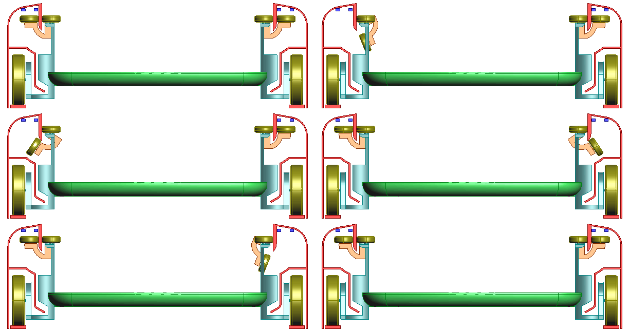
In this figure the fixed guideway cross-section is shown in red and the electrical power rails are indicated by the dark blue rectangles inside the top of the guideway. The partition protects the running surfaces from precipitation and the power rails from any debris that might be thrown up by the drive wheels.
This figure shows how a horizontal branch works (Click on image to see animation )
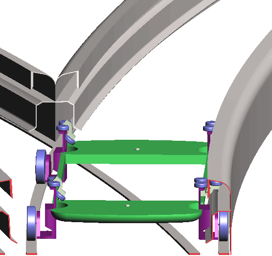
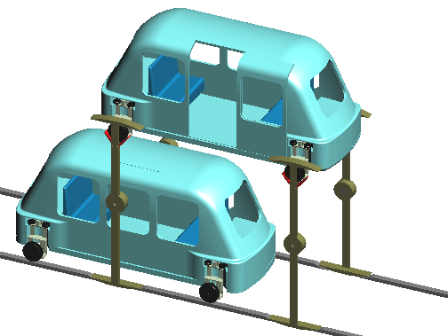
The load wheels project sideways beyond the body of the vehicle which means that they can be used to lift the vehicle vertically as shown in the next three figures.
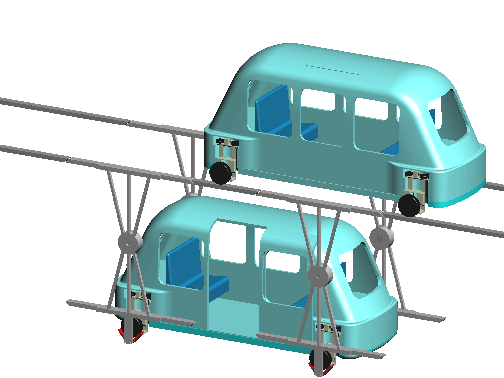
The vehicle to be grabbed by the wheels and swung down to a station at grade. (Click on the image to see animation)
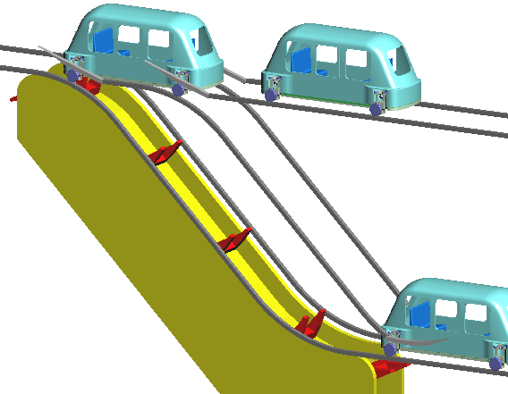
An alternative means of bringing vehicles down to a station at grade from an overhear guideway. (Click on the image to see animation)
MicroRail is similar to this discussion example. The different layout of the power pickup and provision of guidance is not important for this discussion. The wheels in this example are beyond the sides so that they can be used for these vertical movements. The MicroRail tracks look to be less than this and MegaRail greater.
So far we have shown a typical PAT-style four-seat vehicle. Other types with the same wheel geometry are possible:
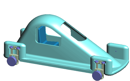
A single seat vehicle with lower aerodynamic drag.
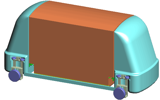
Vehicle carrying a single SSAC
Note that the tracks are separated enough to allow a SSAC to be lowered between them.
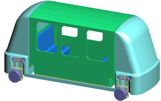
SSAC carrier with a Cabin (a SSAC designed to carry passengers). Using these would allow rapid switching of vehicles between freight and passenger service.
There will be situations where any overhead structure is totally unacceptable and there is no room at grade. Most European cities have areas like this. The only alternative is to put the guideway below the surface. The Both-Sides guideway allows the height of the tunnel to be not much more than the vehicle.
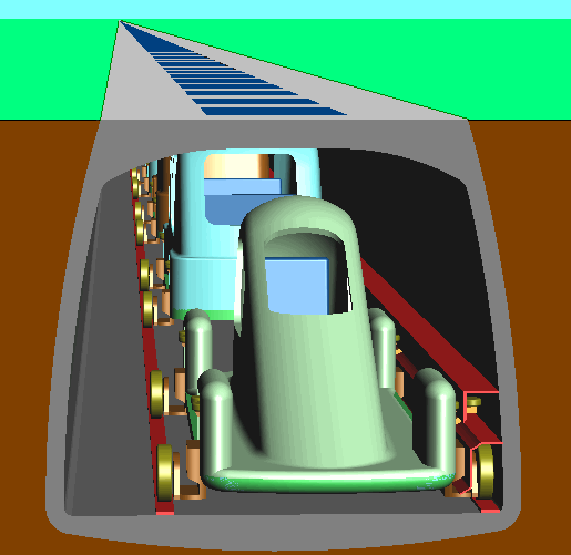
The space on the left provides an escape route. The top of the tunnel is shown level with the ground surface and could have glass bricks in the roof which would provide some light in an emergency.
At stations the the vehicle would be lifted to grade. (Click on figure to see animation )