Here are some ideas for reducing the biggest component of IAUT system cost, the guideway.
As well as the initial capital cost there will be maintenance costs. Tracks will wear away and regular replacements will be a an ongoing cost which could be reduced by the use of low wear ceramic surfaces. Certain types of ceramic can have near zero thermal expansion which could eliminate the need for expansion gaps. The best candidate might be a ceramic with a high content of cordierite, MgO-Al2O3-SiO2. This has no expensive ingredients and is tough and hard. This type of ceramic is sometimes used for refractory bricks.
The track at grade is supported at intervals by the equivalent of the chairs that are used to hold railway lines in position. Smart chairs will have a mechanism for adjusting the height of the track and sensors to detect when adjustment is needed. This will allow the use of minimal foundations and minimise the cost of installation.
Although tunnels do not have the visually intrusion of overhead
A major factor in the cost of new guideway is the foundations. Established roads generally have all sorts of services and other structures underground which have to be avoided and to remain accessible for maintenance.
Previous maintenance activity often results in areas where the fill is not fully compacted and liable to subsidence, which may mean that the foundation needs to go deep to reach stable ground.
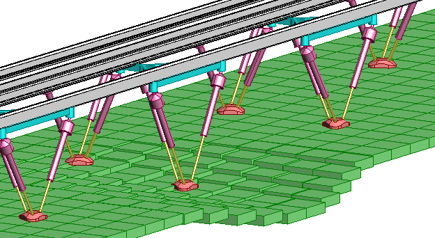
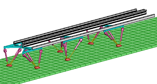
A solution maybe to construct the guideway with sensors that can tell it where it is, and adjustable legs that automatically moves it to where it ought to be.

Click on this figure to see animation of a response to land subsidence.
Active legs would also be used during construction.

Sections of the guideway could be assembled at single site and made to move themselves to their final destination.
On made-up surfaces, such as roads and disused rail track beds, the feet would simply rest on the surface.
When access to services under a foot is needed the foot is ordered to lift and the work carried out. The spacing of the legs and the strength of the guideway is chosen so that it is adequately supported in this situation. If required a temporary beam can be put across a trench and the foot placed on this.
After the work is completed and the trench filled in, the foot is simply put down on top of the fill and the inevitable subsidence is automatically taken care of.
On new uncompacted ground a hole would be dug for each foot, a bag of ballast lowered into it and the foot embedded in this.
The cost of installing a transport link, potentially with the capacity of a motorway, would be very much less than existing alternatives. Where it crosses open country the guideway would be some distance above the ground surface allowing safe and uninterrupted passage to wild-life and farm animals.
If the link becomes redundant, all traces of it can be removed easily and cheaply.
It may become feasible to install a transport link for a one-off event using the sort of temporary footings used for fair-ground rides.
There are three basic types of guideway: suspended, eg Mister and Jpods, beam-supported, eg Vectus and Taxi2000 and "flat surface", eg, Ultra and 2getthere . For this discussion we must dismiss the first two, they need the full guideway regardless of situation and there is little scope for cut-down alternatives.
For a flat surface guideway the minimum requirements are a sufficiently smooth running surface and some form of navigation provision. Vehicles are self steering, unlike supported and suspended guideways which provide mechanical guidance by flanges or sideways guide wheels and need some sort of beacon to provide position references.
There will be a tight specification for the flatness of the running surfaces, probably better than normal road surfaces. This is because low rolling friction will need a combination of low loss tyres and a smooth surface, Also it seems that hub motors, which will be favoured to provide the best drive efficiency, have a limited tolerance of potholes and broken surfaces. We will assume that a dedicated track is required.
Consider a particularly undemanding situation; a straight and level residential suburban street in a "well behaved" neighbourhood. The maximum speed will be about 10 km/hr and vehicles will be fitted with effective collision prevention. The traffic is going to be very light, mainly serving just the residents. There will not be any specific stations, vehicles will stop anywhere along the street, on demand. The residents will accept very occasional suspension of service in extreme weather and will clear snow from the tracks if required.
The track could be made from prefabricated sections supported by smart feet and placed directly on the road surface.
Tracks could even be made of timber and constructed on a DIY basis or assembled like a fairground ride for temporary access to an event.