This section looks at how, given that the SSAC becomes established, it might be used in exploited in novel ways.
One of these is a new class of carriers with a number of SSACs in-line for minimal aerodynamic drag. The point must be made that, while it is easy to devise ways of adapting existing vehicle infrastructure and technology to carry SSACs in this manner, the logistics of feeding a flow of SSACs onto such a new carrier system is an altogether bigger problem and one that will be common to all transport modes.
The other idea is for a seating unit using the SSAC attachments that allows vehicles to be converted rapidly between freight and passenger service.
The proposal is to transport SSACs in a single line on vehicles with a small cross-section. The potential advantages are lower aerodynamic drag, leading to lower energy use at higher speeds. (See also TAMV )
The figure illustrates the fundamental energy losses of various types transport carrying SSACs.
The first curve is for a typical internal combustion engine powered road van carrying a single SSAC and the second for similarly powered a lorry carrying 32 of them. For both of these the engine efficiency is assumed to be 23%, becoming increasingly inefficient at very low speeds.
The rest of the curves assume a hypothetical engine with 80% efficiency. The third and fourth curves show the energy loss for road vehicles carrying a single SSAC and 32 SSACs. The inefficiency of the internal combustion engine relative to alternatives is irrelevant to this study, therefore these curve are the base-line for comparison.
The fourth curve is for a single row of 10 SSACs with a reasonably streamlined head and tail
The fifth curve shows the energy loss for carriage by railway. In this example 400 SSACs are being carried in a train with reasonably good aerodynamics.
The energy loss for all transport modes at low speeds is dominated by rolling friction. The first four examples assume a coefficient of 0.02, typical for current road tyres. An intermediate value of 0.005 is used for curves. The 10 in-line vehicle is assumed to be running on a dedicated guideway with low-loss tyres running on smooth surfaces. These are more lossy than steel-on-steel in railways (coefficient of 0.001 used for curve 6), but quieter and so more suited to urban use.
The energy consumption will be reduced by about a factor of four.
The tracks for light-rail and tram systems are generally by far the most expensive component of these systems. The pattern of passenger demand means that they operate at much less than maximum capacity for most of the time. Even though they may have been installed sufficiently long ago for the initial build cost to have been written off, they still present a valuable but under-exploited asset.
The idea of carrying some freight on passenger services is as old as the railways and is still alive today. For example there is a project to carry some freight on the Amsterdam tram system. The problems are that stations are located at the best places for passengers and not for freight and manual handling of freight would cause unacceptable delays to what is primarily a passenger service.
Automated loading and unloading of SSACs should take less time than is needed for passenger boarding and therefore not cause a delay. Also they can be automatically whisked away from a location which is good for passengers but inconvenient for freight.
PAT (PRT) systems are beginning to be installed and are expected to provide a passenger service which is superior to conventional modes. However their maximum capacity for passengers is limited and, like existing public transport, will have a very uneven passenger demand.
The first is for PAT systems to be used for freight as well as passengers. Freight flowing in and out of an urban centre would be moved mostly during the night when passenger demand is low. The guideway network would be extended to access stations dedicated to handling freight. The SSAC is the right size to fit most of the PAT systems under development and the automatic handling and strong attachment ideal for this application.

Comparison of a PAT-compatible carrier with a typical PAT vehicle
The second is to develop a vehicle to carry, say 10 SSACs, in-line. It would be articulated to allow it to negotiate the tightest curves on the system and the freight stations would be designed to accommodate it.
The third is to develop a version of this vehicle to carry passengers. It would be like the 10 in-line SSAC vehicle but with a four seat cabin instead of SSACs. It would operate in a bus-style service using only part of the network rather than the taxi-like service of PAT. It would be served by stations provided specifically for this type of service.
10 units-in-line vehicle. Click on image to see animation.
This type of vehicle could have a driver and run on the roads, like the road-trains that take tourists around historic sites and amusement parks. It would be capable of taking a considerable volume of freight into areas with restricted access.
A vehicle of this type could also be designed to go on PAT-type guideways The low weight per unit length of PAT vehicles means that the guideway can be much lighter and therefore less expensive and less intrusive than any conventional alternative.
This figure illustrates how SSACs could be re-assigned to multi-unit vehicles going to different destinations. Click on image to see animation.
A further extension of this idea is to substitute passenger cabins for the SSACs. This would allow bus-style operation on particular sections of PAT guideway, in particular through transport bottle-necks. If all the seats were filled, a 10 cabin in-line carrier would carry up to 40 passengers, similar to a conventional bus.
The capacities in the above figure for the "best" 10 cabin in-line vehicle and the "best" PAT are calculated using the same brick-wall headway constraints and operation near the optimum speed. It shows that nearly 10 times as many passengers can be carried and, assuming 0.5 g emergency breaking, similar to the capacity of a light rail or dedicated bus lane.
Running a mixture of PAT and in-line vehicles on the same section of guideway, for example a commuter route, would allow a minimal wait service all the time. At peak times this would be mostly a bus-style service when passenger demand supports service intervals of a few minutes and off-peak it would be an on-demand PAT service. This would avoid having to run nearly empty vehicles off-peak just to provide an acceptable service.
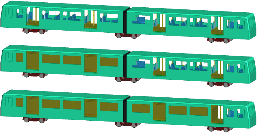
The proposals above suppose two fleets of vehicles, one for passengers, the other for freight. By itself this would allow greater exploitation of the major asset of the system, the track, road or guideway. The proposal here is to use the same vehicle for both freight and passengers, using seating units which fit into the same space as a SSAC using the same attachment and handling features.

A Metro vehicle configured for:- top: all passengers, middle: half passengers and half SSACs, bottom: nearly all SSACs with space for a few passengers.

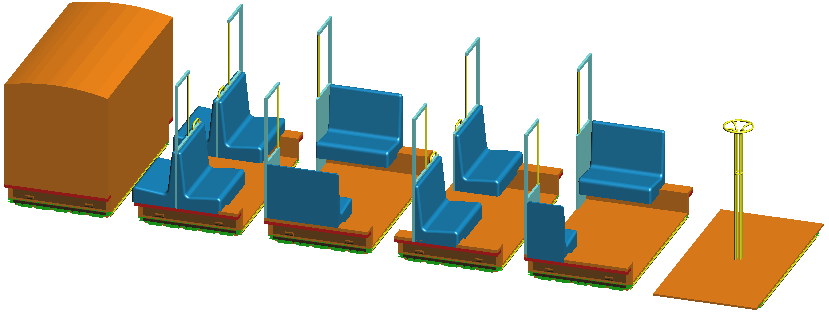
Seating is provided by a set of seating units. The passenger furniture is mounted on a tray which has the same attachment features as a SSAC. The seating units might extend beyond the SSAC envelope and would be confined to the Metro system.

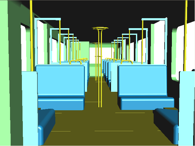
View of seating units inside a hypothetical vehicle loosely based on the Tyne and Wear Metro

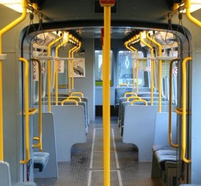
Inside a Tyne and Wear metro carriage
Once the SSAC becomes established for current transport modes, it will enable novel types of transport to be developed, with dramatically lower installation cost and energy demand while providing a significantly superior service.