Most PAT schemes propose to have all or most of the guideway elevated. This has considerable advantages of avoiding malicious activity and obstructive structures at grade.
However, this means that at stations the vehicles are elevated and the passengers are at grade. The usual answer is to have an elevated station to which passengers are conveyed by stairs and lifts (elevators). This means that the station becomes a substantial structure which:
The proposal is to bring the vehicles down to the passengers rather than the passenger up to the vehicle. This can of course be done with ramps but, unless they are rather steep, they will block off an unacceptable area at grade.
The mister system uses ramps with a slope of 45° and stations at grade. The stations will have a reasonably small footprint and therefore allow more of them with shorter spacing; the PAT ideal.
The spreadsheet models for these configurations are included in the list on the previous page
A vertical lift will have a minimal footprint at grade and would probably have a lower load specification than the passenger lift for an elevated station.
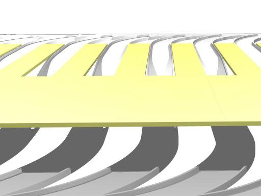
Click on figure for animated version

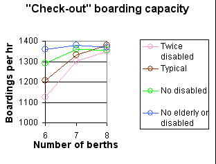
The points for 8 berths are for two ranks of 4 in parallel and, for 9 berths, 3 ranks of 3 berths.
The figure below shows this type of berthing with ramps rather than lifts. The arriving vehicles are come up from below. Because they are empty they are light and passenger comfort is irrelevant and therefore the slope can be steeper. In the examples I have assumed a slope of 20%. However if the maximum slope was much less than this, say 10%, the ramps would probably take up an excessive area. This would be particularly the case where they are coming down from an elevated guideway. This would mean that passenger have to walk down a narrow passage between the ramps, which could be rather oppressive.

Link to an animated illustration (640 Kb).
The iterative model of this configuration should be equally valid for both ramps and lifts.

The graph shows the throughput for 6, 7 and 8
berths. In the model what happens is that the first 5 berths are used
non-stop and take up nearly all the incoming empty vehicles leaving
rapidly fewer to reach the last few berths.
The idea here is that there would always be extra Cabins, probably two, remaining at the berth. The carrier would always deposit one Cabin and pick up another as shown in this animation :

The advantages of this arrangement are:

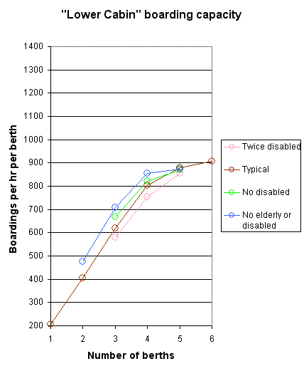
As can be seen the flow of traffic along one guideway with this type of berth is limited by the through route being blocked for the time it takes for the Cabin or vehicle to be lowered and the guideway to be clear. However the efficiency for up to four berths is good. We propose that two sets of four berths in parallel would be an elegant configuration.
Note that when there are no passengers using the berth, the optimum wait state will depend on whether the next expected passenger is for boarding or alighting. For boarding the wait state will be as in the figure above. For alighting it would be as below. Vehicles move from left to right in both cases:

Normally alighting would take precedence over boarding.
If the berth is used for both, there could be a situation where the alighting passenger has to wait for boarding to complete. One option would be to allow alighting but not boarding from the first Cabin position, then there could be the situation where the departure of the boarded Cabin would be delayed waiting for the alighting to be complete.
A sensible arrangement would be for a low-use station to have two berths, one with a normal wait state for alighting and the other for boarding.